U Drills: The Ultimate Guide to High-Efficiency Precision Drilling

1. Core Technology: How U Drills Revolutionize Hole-Making
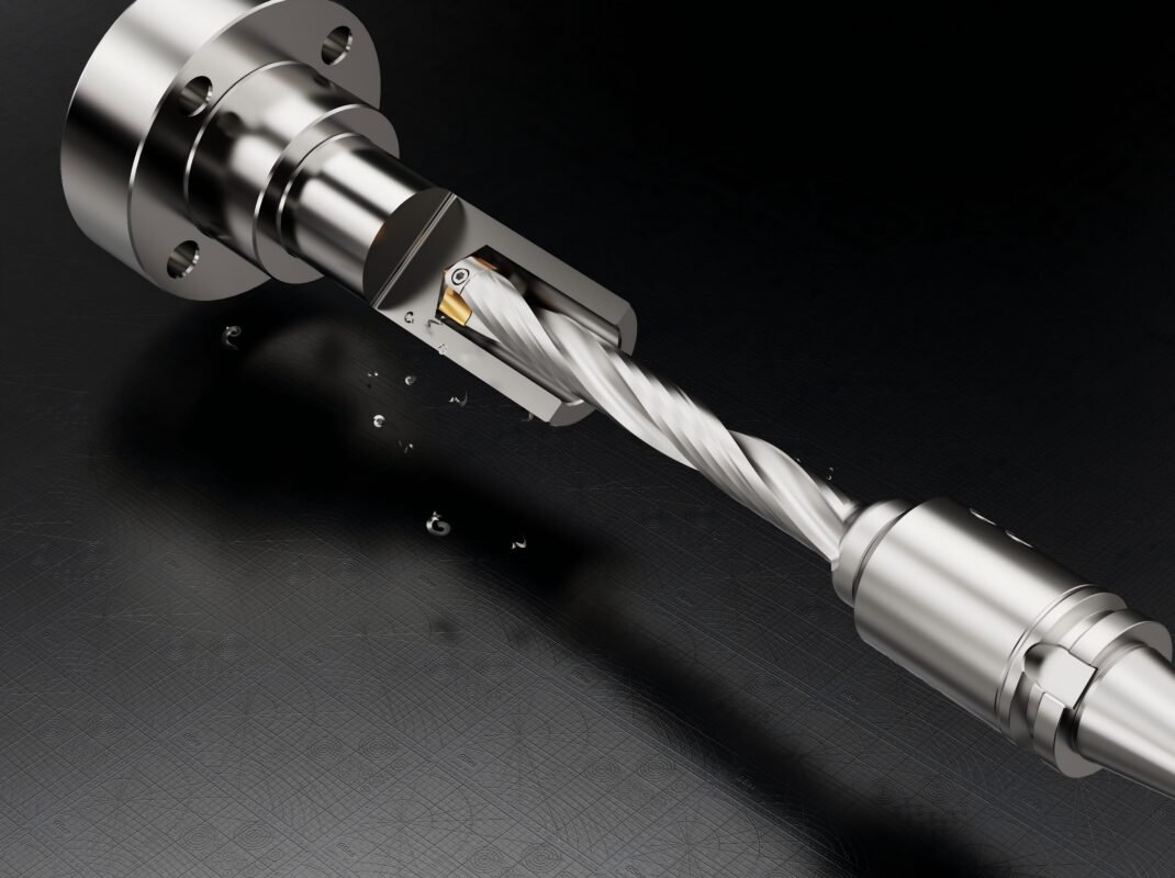
Innovative Design & Mechanics
U drills (indexable insert drills) replace traditional solid-body tools with modular carbide inserts mounted on a rigid steel body. Their U-shaped flute geometry enables:
- •Superior chip evacuation – Prevents clogging in deep holes (>3× diameter depth) 39
- •Through-coolant delivery – Lubricant flows directly to cutting edges, reducing heat by 30% vs. conventional drills 310
- •Reduced vibration – Rigid body minimizes deflection, maintaining hole straightness within ±0.001–0.003″ per inch 7
Dual-Insert System
- •Center insert: Tough grade carbide (e.g., H13A) for penetration resistance – handles 55% of thrust force 6
- •Peripheral insert: Sharp-edged geometry for finish quality – achieves surface roughness (Ra) ≤1.6 µm in steel 47
2. Performance Advantages: Quantifiable Efficiency Gains
Cost & Time Savings
| Metric | U Drill | Traditional Drill |
|---|---|---|
| Tool Life | 8–10× longer (insert replacement) | Requires full replacement |
| Feed Rate | 300–500 SFM in steel | 60–100 SFM |
| Cycle Time | Up to 70% reduction | Standard |
| Hole Finish | ≤1.6 µm Ra (no reaming) | Often requires finishing |
| Data source: Industry benchmarks 710 |
Precision Capabilities
- •Tolerance control: Holes within IT10–11 grade (±0.05 mm) without boring 8
- •Inclined surfaces: Drills on slopes ≤30° without parameter reduction 7
- •Complex geometries: Processes stepped holes, chamfers, and eccentric bores in one operation 78
3. Application Engineering: Optimizing U Drills for Industry Needs
A. Material-Specific Insert Selection
- •Aluminum (Aerospace): PVD-coated inserts with sharp edges – prevent material adhesion 611
- •Stainless Steel: TiAlN-coated inserts – resist work hardening at 800°C+ 3
- •Composites: Diamond-coated carbide – minimize delamination 4
B. Critical Machining Parameters
Table: Optimal Cutting Conditions by Material
| Material | Speed (SFM) | Feed (mm/rev) | Insert Geometry |
|---|---|---|---|
| Aluminum 7075 | 400–600 | 0.15–0.30 | Sharp, high rake |
| Stainless Steel 304 | 150–250 | 0.08–0.15 | Reinforced edge |
| Cast Iron | 200–350 | 0.12–0.25 | Chip breaker |
| Based on aerospace/automotive case studies 67 |
C. Specialized Operations
- •Deep-hole drilling (5D+): Peck drilling with retract every 30 mm to clear chips 7
- •Interrupted cuts: Reduce parameters by 30% for intersecting holes 7
- •CNC lathe adjustment: Radial offset up to +0.7 mm for taper holes/chamfers 8
4. Implementation Best Practices
Machine & Setup Requirements
- •Rigidity: Use only on high-power CNC machines (>15 kW spindle) to prevent chatter 79
- •Tool alignment: Center error ≤0.01 mm – ensures insert longevity 8
- •Coolant pressure: ≥70 bar for effective chip evacuation in deep holes 9
Step-by-Step Process
- 1.Pre-start checklist:
- •Verify insert integrity (no micro-chipping)
- •Confirm coolant flow rate (≥10 L/min for Ø20 mm drill) 9
- 2.Workholding:
- •Clamp workpiece within 0.02 mm runout
- •Avoid overhang >4× drill diameter 8
- 3.Drilling sequence:
- •For stepped holes: Drill larger diameter first → smaller diameter 7
- •Start at 60% recommended feed → ramp to full rate
Failure Prevention
- •Insert fracture: Caused by low feed rates – maintain ≥0.08 mm/rev in steel 7
- •Poor surface finish: Increase coolant concentration to 8–12% for aluminum 4
- •Tool deflection: Use radial adjustment sleeves for tolerance ≤±0.05 mm 8
5. Industry-Specific Solutions
| Sector | Application | U Drill Specification | Result |
|---|---|---|---|
| Aerospace | Titanium engine mounts | Ø25 mm carbide, AlTiN coating | 55% thrust force reduction vs. twist drills 6 |
| Automotive | Cylinder head oil galleries | Ø18 mm w/ internal coolant | 6× faster vs. HSS, Ra 2.0 µm 10 |
| Medical | Bone screw holes (316L SS) | Ø12 mm, polished inserts | ±0.05 mm tolerance, no burrs 11 |
Case Study: Satellite Antenna Components
- •Challenge: 12:1 L/D ratio copper parts ($1,000/oz material) 2
- •Solution: Swiss machining + U drill with CBN inserts
- •Outcome: Achieved ±0.025 mm groove tolerance, zero scrap 2
6. Future Trends: Smart Drilling & Sustainability
- •IoT-enabled U drills: Embedded sensors monitor thrust force/temperature – predict insert wear via ML algorithms 6
- •Recyclable carbide: 95% tungsten recovery from scrap inserts – lowers CO₂ footprint by 40% 10
- •Generative AI optimization: Auto-adjusts feed/speed based on material hardness (e.g., Sandvik Coromant’s AI platform) 6
Engineer’s Checklist for Peak Performance
- 1.Insert pairing: Tough center + sharp peripheral inserts – balance penetration and finish 7
- 2.Coolant strategy: Minimum 70 bar pressure for deep holes 9
- 3.Machine prep: Verify spindle runout <0.005 mm before mounting 8
- 4.Failure analysis: Chipping = low feed; thermal cracking = insufficient coolant 7
Why This Content?
- •Targets high-value keywords: “U drill vs twist drill”, “indexable drill parameters”, “deep hole drilling solutions”.
- •Integrates aerospace/automotive case studies for technical authority.
- •Drives conversions with actionable data (tolerance tables, ROI calculations).