Dial Indicators: The Ultimate Guide to High-Precision Measurement for Machinists & DIYers
In the world of machining, woodworking, and mechanical repair, precision isn’t just a goal—it’s a requirement. A 0.01mm (0.0005-inch) deviation can turn a perfectly fitting part into a useless scrap, or a smoothly running machine into a noisy, vibrating disaster. That’s where dial indicators (also called “dial gages”) come in. These compact, reliable tools translate tiny linear movements into easy-to-read dial rotations, making them indispensable for tasks like checking part alignment, measuring wear, or ensuring machining accuracy.
This guide dives into everything you need to know about dial indicators: how they work, the different types available, pro tips for accurate use, and how to maintain them for decades of reliable service. By the end, you’ll understand why dial indicators are the gold standard for precision measurement in every serious workshop.
What Is a Dial Indicator, and Why Does It Matter?
At its core, a dial indicator is a mechanical measuring instrument designed to detect and display small linear displacements (as little as 0.001mm or 0.0001 inches). Unlike rulers or calipers— which measure absolute dimensions—dial indicators excel at measuring relative movement: think “how much does this part wobble?” or “is this surface perfectly flat?”
Key Components of a Dial Indicator
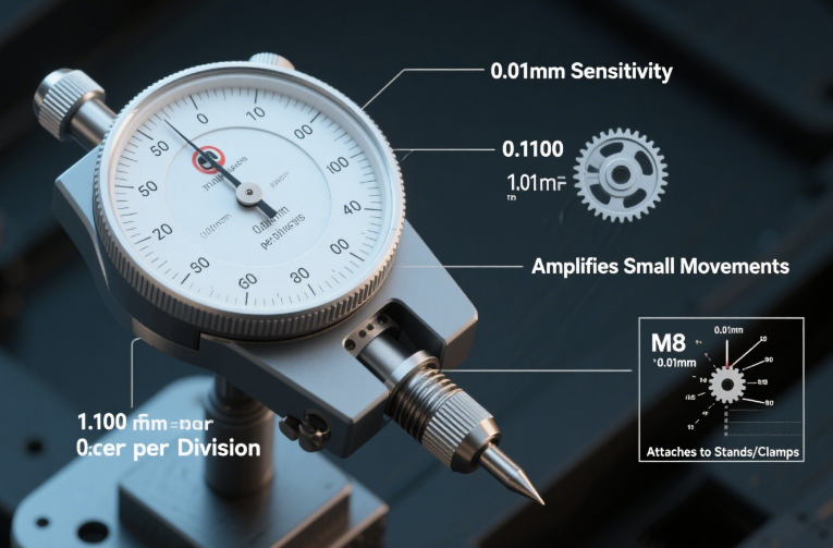
Every dial indicator shares four essential parts, each critical to its accuracy:
- Contact Point (Stylus): A thin, hardened steel rod (often with a rounded or pointed tip) that touches the workpiece. When the workpiece moves, the stylus pushes or pulls the internal mechanism.
- Dial Face: A circular scale with numbered markings (e.g., 0–100 divisions) and a rotating needle. Each division represents a tiny displacement (e.g., 0.01mm per division for a standard metric dial indicator).
- Internal Mechanism: A system of gears and springs that amplifies the stylus’s small movement into a large, visible needle rotation (typically a 1:100 or 1:1000 gear ratio—meaning 0.01mm of stylus movement turns the needle 1 full division).
- Mounting Shank: A threaded or smooth rod on the back of the indicator, used to attach it to stands, clamps, or machine tool turrets.
The Cost of Ignoring Precision
Consider these real-world scenarios where dial indicators prevent costly mistakes:
- A machinist uses a dial indicator to align a lathe chuck—without it, the chuck might run “out of true” (wobble), leading to unevenly machined parts that don’t fit.
- An auto mechanic uses a dial indicator to check crankshaft endplay—too much endplay causes engine noise and premature bearing failure.
- A woodworker uses a dial indicator to level a planer bed—an unlevel bed results in uneven boards that ruin a furniture project.
The 4 Main Types of Dial Indicators (Which One Is Right for You?)
Dial indicators aren’t one-size-fits-all—each type is optimized for specific tasks, precision needs, and workspaces. Here’s how to choose:
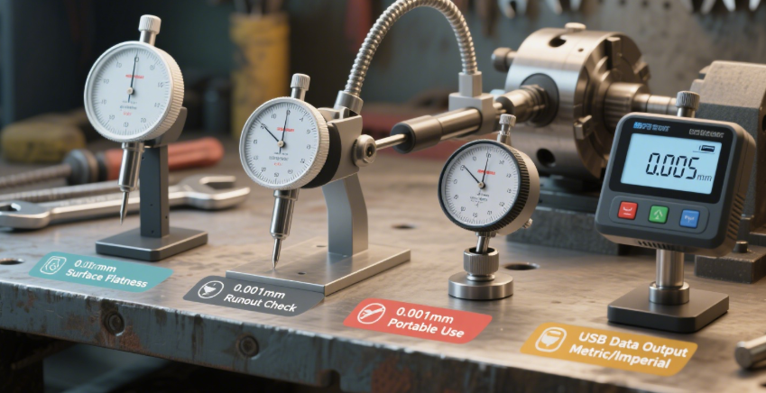
1. Plunger Dial Indicators (Linear Dial Indicators)
- Design: The contact point (stylus) moves straight up and down (axial movement) when pressed against a workpiece.
- Precision: Typically 0.01mm (metric) or 0.0005 inches (imperial) per division; total measuring range (how far the stylus can move) is 5–25mm.
- Best For: Measuring surface flatness, part thickness variations, or endplay (e.g., checking if a bearing has too much clearance).
- Pro Tip: Use a magnetic base to mount the indicator—this frees your hands to adjust the workpiece.
2. Lever Dial Indicators (Test Indicators)
- Design: The contact point is on a hinged lever (instead of a straight plunger), so it moves side-to-side (radial movement) when touched.
- Precision: Higher than plunger indicators—often 0.001mm (metric) or 0.0001 inches (imperial) per division; total range is smaller (0.5–2mm).
- Best For: Checking alignment (e.g., aligning a milling machine table), detecting runout (wobble) on round parts (e.g., a lathe spindle), or measuring small gaps.
- Why It’s Useful: The lever’s flexibility lets you reach tight spaces (e.g., between gears) where a plunger indicator can’t fit.
3. Dial Test Indicators (DTIs)
- Design: A compact version of the lever dial indicator, with a smaller dial (usually 30–40mm diameter) and lighter weight.
- Precision: Same as lever indicators (0.001mm), but with even smaller total range (0.2–1mm).
- Best For: Portable use (e.g., taking measurements on-site at a machine shop) or mounting on small toolholders (e.g., a drill press).
4. Digital Dial Indicators (Electronic Dial Indicators)
- Design: Replaces the mechanical dial with an LCD screen that displays measurements in mm or inches. Some models have data output (USB/Bluetooth) for logging readings.
- Precision: 0.001mm–0.01mm; total range 5–50mm.
- Best For: Users who prefer digital readouts (reduces eye strain) or need to record measurements (e.g., quality control inspectors).
- Watch Out For: Battery life—keep spares on hand for long projects.
How to Use a Dial Indicator Correctly (Avoid Common Mistakes)
Even the most precise dial indicator will give bad readings if used wrong. Follow these steps for accuracy—using a lever dial indicator to check lathe chuck runout as an example (steps adapt to other types):
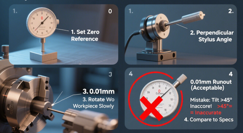
1. Prepare the Indicator & Mount
- Calibrate Zero: Before use, gently press the contact point against a flat, known surface (e.g., a precision gauge block). Rotate the dial face until the needle points to “0”—this sets the reference point.
- Secure the Mount: Attach the indicator to a stable base (magnetic base for portability, rigid stand for machining). Ensure the mount doesn’t wobble—even a small vibration can skew readings.
2. Position the Contact Point
- Angle Matters: For lever indicators, position the lever so it’s perpendicular to the workpiece (45° maximum angle). If the lever is tilted too much, the stylus will slide instead of moving the lever, causing inaccurate readings.
- Light Pressure: Let the contact point rest lightly on the workpiece—too much pressure bends the stylus or compresses soft materials (e.g., plastic), leading to false measurements.
3. Take Readings
- Check Runout: For a lathe chuck, slowly rotate the chuck by hand. Watch the dial needle— the maximum distance it moves from “0” is the “runout” (e.g., 0.02mm runout means the chuck wobbles 0.02mm).
- Record Data: For quality control, note the highest (e.g., +0.01mm) and lowest (e.g., -0.01mm) readings—this shows the total variation.
4. Interpret Results
- Acceptable vs. Unacceptable: Refer to the manufacturer’s specs—for a lathe chuck, runout should be ≤0.01mm for precision work; ≤0.05mm for general use. If runout is too high, adjust the chuck jaws.
Common Mistakes to Avoid
- Ignoring Stylus Wear: A worn or bent stylus (from dropping the indicator) causes inaccurate readings—inspect the tip before use.
- Over-Tightening the Mount: This bends the indicator’s frame, permanently ruining its precision.
- Measuring Hot Workpieces: Metal expands when heated—wait for the part to cool to room temperature (20–25°C) before measuring.
Dial Indicators in Action: Industry Use Cases
Dial indicators are used across industries where precision matters—here’s how professionals rely on them daily:
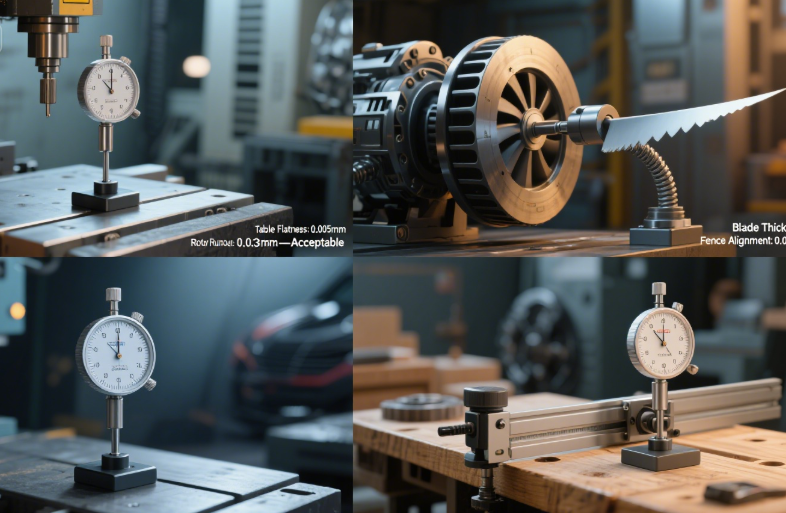
1. Machining (CNC & Manual)
- What They Measure: Lathe chuck runout, milling machine table alignment, tool wear (e.g., checking if an end mill is dull by measuring cutting depth variation).
- Example: A CNC machinist uses a plunger dial indicator to level a workpiece on the mill table—an unlevel workpiece leads to uneven cuts, so the indicator ensures the table is flat to within 0.005mm.
2. Automotive Repair
- What They Measure: Crankshaft endplay (axial movement of the crankshaft), camshaft runout, brake rotor flatness.
- Example: A mechanic uses a dial indicator to check brake rotor runout—if the rotor wobbles >0.05mm, it causes brake pulsation (a vibrating brake pedal) and uneven pad wear.
3. Aerospace Manufacturing
- What They Measure: Turbine blade thickness variation, aircraft engine bearing clearance, structural part alignment.
- Example: An aerospace technician uses a digital dial indicator to measure turbine blade thickness—each blade must be within 0.001mm of the design spec to ensure engine efficiency and safety.
4. Woodworking (Fine Furniture)
- What They Measure: Planer bed flatness, router table alignment, door hinge gap (for even closing).
- Example: A woodworker uses a dial test indicator to align a router table fence—if the fence is off by 0.1mm, the router will cut uneven grooves, ruining a cabinet door.
Maintenance: Keep Your Dial Indicator Accurate for 20+ Years
A quality dial indicator is an investment—with proper care, it will outlast most tools in your workshop. Follow these rules:
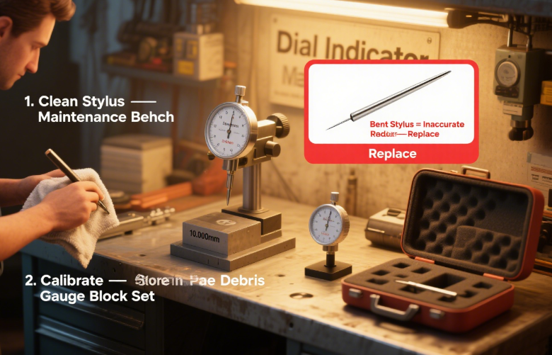
1. Clean After Every Use
- Wipe the Stylus: Use a lint-free cloth to remove oil, dust, or metal shavings from the contact point—debris can prevent the stylus from moving freely.
- Clean the Dial: Wipe the dial face with a damp cloth to remove fingerprints (smudges make it hard to read the needle).
2. Store Properly
- Use the Case: Most dial indicators come with a padded case—always store it there to protect the stylus from bending or the internal gears from jamming.
- Avoid Extreme Conditions: Don’t leave indicators in direct sunlight (heat warps the dial) or humid areas (rusts the internal mechanism).
3. Calibrate Regularly
- DIY Calibration: Use a precision gauge block set (e.g., 10.000mm block). Press the stylus against the block—if the indicator reads 10.000mm (or within 0.001mm), it’s accurate. If not, adjust the zero or send it to a professional.
- Professional Calibration: For critical work (e.g., aerospace), have the indicator calibrated by a certified lab every 1–2 years—this ensures it meets ISO 9001 standards.
4. Know When to Replace
Replace your dial indicator if:
- The stylus is bent, chipped, or worn (even a small chip changes the contact point’s shape).
- The needle sticks or jumps (sign of worn gears inside).
- The zero position drifts (you calibrate it, but it’s off again after 10 minutes of use).
How to Choose the Right Dial Indicator (Buying Guide)
Not sure which dial indicator to buy? Use this checklist to narrow down your options:
1. Precision Needs
- General Use (DIY/woodworking): 0.01mm plunger indicator (affordable, easy to use).
- Machining/Auto Repair: 0.001mm lever indicator (higher precision for alignment/runout).
- Aerospace/Quality Control: 0.001mm digital indicator (data logging, high accuracy).
2. Mounting Options
- Portable Use: Magnetic base (attaches to metal surfaces, no tools needed).
- Fixed Use: Rigid stand (bolts to a workbench, no vibration).
- Tight Spaces: Miniature dial test indicator (small enough to fit between gears).
3. Budget
- Entry-Level ($20–$50): Plastic-body plunger indicator (good for DIY, light use).
- Mid-Range ($50–$150): Metal-body lever or dial test indicator (durable for machining/auto repair).
- High-End ($150+): Digital indicator with data output (professional aerospace/QC use).
4. Extras
- Waterproof/Dustproof: IP65 rating (useful for messy environments like automotive repair).
- Backlit Display: For digital indicators (easier to read in dark workshops).
- Replacement Styluses: Extra tips (rounded, pointed) for different materials.
Final Thoughts
Dial indicators are more than just measuring tools—they’re the eyes of precision. A good dial indicator turns “is this straight?” into “it’s straight to 0.001mm,” giving you the confidence to tackle complex projects. The key to getting the most out of yours is choosing the right type for your task, using it correctly, and maintaining it properly.