Dial Indicators (Dial Gauges) in Hardware: Specifications, Uses, and Applications
Dial indicators—often called dial gauges—are precision measuring tools that excel at detecting tiny dimensional changes, making them indispensable in machining, manufacturing, and quality control. With their ability to measure deviations as small as 0.01mm (or 0.0001 inches), they ensure parts meet strict tolerances and machinery runs smoothly. This blog explores their specifications, how to use them, and where they shine in real-world scenarios.
1. Key Specifications: Choosing the Right Dial Indicator
Dial indicators vary in design to suit different tasks, with core specifications dictating their use cases:
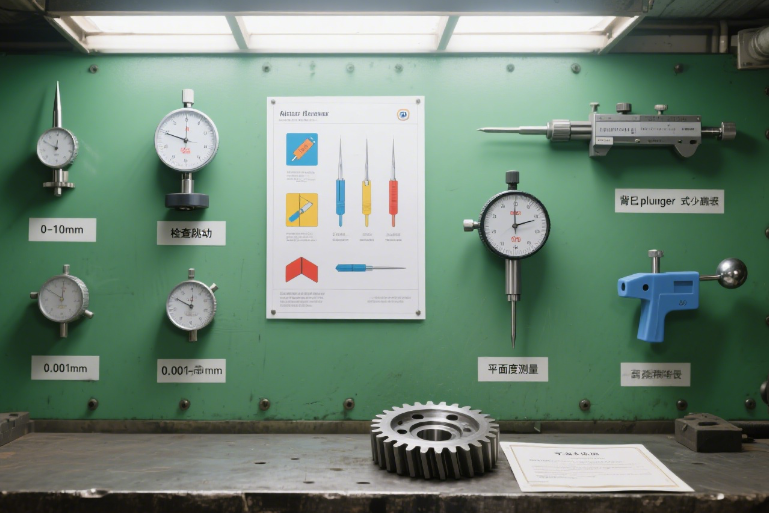
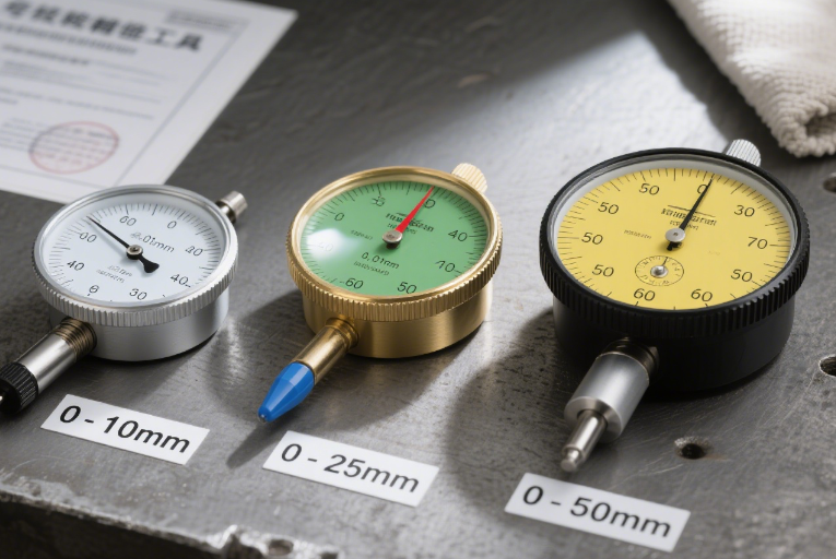
Measuring Range
- Small Range (0–10mm): Ideal for checking runout (e.g., a rotating shaft’s wobble) or small part tolerances.
- Medium Range (0–25mm): Versatile for general-purpose measurements, such as gap checks or component alignment.
- Large Range (0–50mm+): Used for larger workpieces, like checking flatness across a metal plate or door alignment.
Accuracy
Most dial indicators offer 0.01mm (0.0004 inches) accuracy, though high-precision models reach 0.001mm (0.00004 inches) for aerospace or medical part inspections.
Mounting Options
- Magnetic Base: Attaches to metal surfaces (e.g., machine beds) for hands-free use.
- Universal Stand: Clamps to workbenches, with adjustable arms for flexible positioning.
- Back Plunger: For measuring holes or recesses, where the tip extends into tight spaces.
Tip Styles
- Flat Tips: For measuring flat surfaces or edges.
- Pointed Tips: Ideal for grooves, slots, or uneven surfaces.
- Ball Tips: Reduce surface damage on soft materials like plastic or brass.
2. How to Use a Dial Indicator: Step-by-Step
Using a dial indicator requires careful setup to ensure accuracy. Here’s a standard workflow:
- Mount the Indicator: Secure it to a magnetic base or stand, positioning the tip perpendicular to the workpiece surface.
- Zero the Gauge: Bring the tip into light contact with the workpiece (until the needle moves slightly). Rotate the dial face so the “0” aligns with the needle—this sets your reference point.
- Take Measurements: Move the workpiece (or the indicator) across the area to be checked. The needle will fluctuate, showing deviations from the zero point. For example, a needle moving to “+0.03mm” means the surface is 0.03mm higher than the reference.
- Record Readings: Note the maximum and minimum values to assess total runout, flatness, or alignment.
Pro Tip: Always clean the workpiece and indicator tip first—dust or debris can skew results.

3. Primary Applications: Where Dial Indicators Shine
Dial indicators are versatile tools, critical in scenarios where precision is non-negotiable:
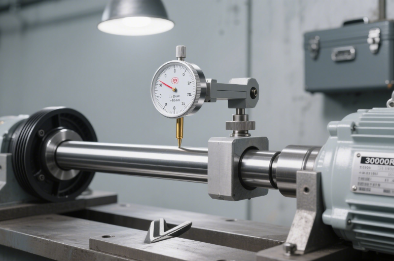
Checking Runout
Runout measures how much a rotating part (e.g., a shaft, pulley, or gear) wobbles. A dial indicator tip pressed against the rotating part will show fluctuations, helping identify bent shafts or misaligned components.
Example: Inspecting a car axle—excessive runout (over 0.05mm) can cause vibrations or uneven wear.
Ensuring Flatness
Flatness checks verify if a surface is perfectly level. By moving the indicator across the surface (e.g., a metal plate or machine bed), you can detect high or low spots.
Example: A mold maker ensuring a plastic injection mold’s surface is flat within 0.02mm to prevent uneven part cooling.
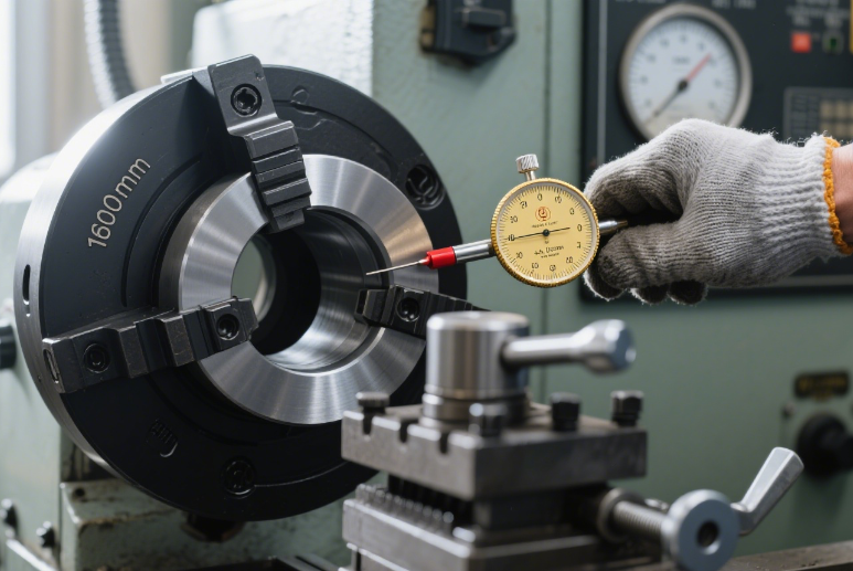
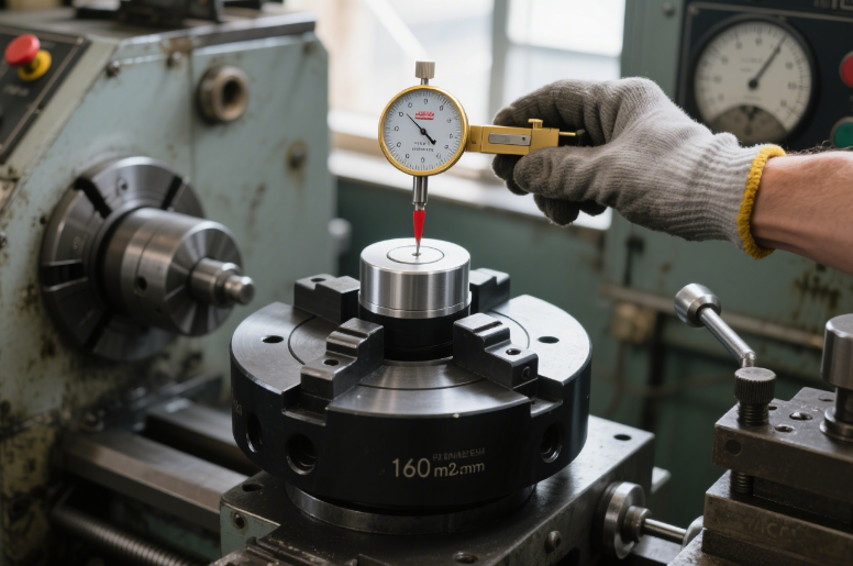
Aligning Machinery
Dial indicators help align components like lathe chucks, milling machine tables, or conveyor belts. By measuring gaps or offsets, you can adjust parts to ensure they’re perfectly parallel or concentric.
Example: Aligning a lathe chuck—misalignment (over 0.01mm) can result in unevenly turned parts.
Quality Control Inspections
In manufacturing, dial indicators verify that finished parts meet design tolerances. For example, checking if a bolt’s shank diameter is within 0.01mm of the specified size.
Example: A quality inspector measuring a precision bearing—any deviation from 0.005mm can affect its performance.

4. Choosing the Right Dial Indicator
- For small parts or runout checks: Use a 0–10mm range with a pointed tip.
- For large surfaces or flatness checks: Opt for a 0–50mm range with a flat tip and universal stand.
- For tight spaces (e.g., holes): Choose a back plunger model with a slim tip.
- For high-precision tasks (aerospace): Select a 0.001mm accuracy model.
With the right dial indicator, you can catch tiny imperfections before they become costly errors—whether you’re a professional machinist or a DIY enthusiast building precision projects.